Hidden Pitfalls in Sensor Calibration: Field Engineer's Essential Guide
Sensor calibration can make or break your operations and prevent disasters that get pricey. Companies lose thousands in revenue and efficiency when their systems go down, even for a second. Many engineering teams see calibration as just another checkbox instead of their best defence against sensor drift, expensive errors and compliance issues.
Field instruments often show wrong readings because of calibration problems that develop during long-term use. Temperature sensors struggle to stay accurate in harsh, high-temperature environments. These hidden issues pile up silently over time. The biggest challenge comes from sensor drift problems that sneak up quietly—usually discovered only after causing major damage.
Our team of industry experts brings over 65 years of combined automation and calibration experience. We created this detailed guide about inertial sensor calibration techniques to help you dodge common mistakes. You’ll learn the best ways to protect your operations and profits, whether you work with temperature sensors that need ±0.1°C to ±1.0°C accuracy in industrial applications or other critical instruments.
Ignoring Sensor Drift in Harsh Environments
Sensor drift poses a quiet threat to measurement accuracy in industrial environments. Readings gradually change even under identical conditions, which creates a widening gap between actual values and recorded outputs. Field engineers must think over and deal with drift. This becomes a vital concern in challenging operating conditions where accuracy directly affects process quality and safety.
Drift Patterns in Thermocouples vs RTDs
Temperature sensors react differently to environmental stressors. RTDs and thermocouples show distinctly different stability profiles in the largest longitudinal study. RTDs typically keep their calibration longer because of their stable design. Thermocouples show more noticeable drift patterns, which we traced to chemical changes like oxidation within the sensor element.
Lab tests reveal these differences clearly. One study tracked 126 RTDs over two years. The results showed 63 units drifted more than 0.1°C, while 46 drifted up to 1°C. These numbers are nowhere near as severe as thermocouples. All but one of these 66 tested units drifted by at least 1.4°C in just six months. One unit showed a concerning 9.9°C deviation.
Thermocouples don’t deal very well with several degradation mechanisms:
- Thermoelectric inhomogeneity
- Junction deterioration
- Insulation resistance breakdown
Recommended Calibration Intervals for Industrial Use
Setting up proper calibration schedules means weighing multiple factors. Industrial sensors just need calibration checks at least yearly where average accuracy suffices. Systems that demand higher precision should undergo checks every six months.
These environmental factors might call for more frequent calibration:
- Temperature extremes (0-100°C)
- High humidity (up to 100% RH)
- Mechanical vibration and shock
- Any combination of these stressors
The measurement’s criticality should shape your calibration strategy. My experience as a field engineer suggests an all-encompassing approach. This approach weighs what it all means of measurement errors against the sensor’s past stability. Manufacturers rarely specify calibration periods due to varying applications. Your best bet is to work closely with your sensor supplier to determine optimal intervals based on your specific operating conditions.
Using Uncertified or Aged Reference Sensors
Reference sensors are the life-blood of every calibration system. People often take their reliability for granted. These reference tools’ quality determines if all subsequent measurements are valid. This makes proper certification and maintenance crucial.
Traceability Standards for Reference Probes
Your instruments need an unbroken chain of comparisons to national or international standards. This connection ensures measurements associate with recognised standards that have quantified uncertainty levels. Equipment calibrated at a national metrology institute isn’t enough. You need proper documentation of the entire calibration chain.
Certified Reference Materials (CRMs) are crucial. They confirm measurement systems follow specified procedures. Calibration laboratories must maintain these reference materials with proven traceability to meet ISO 17025:2005 requirements.
Effect of Reference Sensor Degradation on Accuracy
Both systematic and random errors increase as reference sensors age. A study revealed that ignoring sensor degradation led to major errors in remaining useful life (RUL) estimation. These errors affected maintenance decisions.
Sensor stability remains the biggest concern. Less drift means lower measurement uncertainty. Research shows that calibrated low-cost sensors lose measurement precision over time. Their calibration equations show noticeable changes after several months of use.
So, reference sensors need regular verification against higher standards. Field engineers should follow these practises with older reference equipment:
- Check if calibration certificates show an unbroken chain to SI units
- Document uncertainty values at each calibration point
- Schedule frequent calibrations for aged reference sensors
Field teams can use virtual in-situ calibration methods to identify and fix both systematic and random errors without disrupting operations.
Skipping Stabilisation Time During Calibration
Rushing the calibration process before sensors reach thermal equilibrium leads to inaccurate results. Engineers often underestimate how long it takes to get stable readings.
Thermal Equilibrium in Liquid Bath Calibrators
Liquid bath calibrators deliver excellent temperature stability and uniformity to ensure precise calibration. Notwithstanding that, they take their time to reach thermal equilibrium. The bath fluid in overflow basins moves from bottom to top and creates an even temperature spread with steady timing. While stirred liquid baths work well to maintain steady temperatures, temperature gradients can still show up even in the best conditions. Both reference and test thermometers need similar horizontal positions during calibration to get accurate results.
Multi-sensor Setup Considerations
Multi-sensor calibration setups just need extra time to stabilise before you record any values. Standard protocols usually ask for a 3-minute wait between setting temperature and taking readings. But this set time isn’t enough, especially when sensors have longer time constants. Studies show that operational contamination changes sensor time constants by a lot. Here’s what you should think over before calibration:
- Test to find each sensor’s time constant
- Change waiting times based on what you measured
- Remember that quick jumps between test points can hurt accuracy
When time constants aren’t crucial, you can adjust the waiting time after setting temperatures for each sensor.
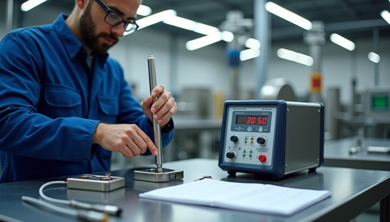
Incorrect Sensor Placement in Calibration Blocks
Sensor positioning in calibration blocks determines the success of your calibration results. Small placement errors can affect measurement accuracy and lead to false readings and failed calibrations.
Insertion Depth Guidelines for Dry-block Calibrators
Temperature readings depend on proper immersion depth. The standard practise requires temperature sensors to be immersed at least 10-15 times their diameter. Temperatures below 350°C need the 10× diameter guideline, while those above 350°C follow the 15× diameter recommendation. To cite an instance, a 6mm sensor needs minimum immersion of 90mm at high temperatures.
Reference and test sensors should line up at similar depths, and their sensing elements’ centres should be positioned horizontally parallel. Different temperatures at varying heights within the block will create measurement errors without this alignment.
Sleeve Fit and Heat Transfer Efficiency
The calibration quality depends on the sleeve-to-sensor fit. Users should select inserts with proper hole diameters that let sensors fit snugly with minimal lateral movement. Air gaps from loose fits block heat transfer and cause erroneous readings.
Many believe that oils or thermal greases enhance heat transfer between the sensor and block. These substances damage vital components including heaters, sensing PRTs, and cooling systems. The quickest way to achieve optimal heat conduction is proper sleeve selection that ensures good contact between the sensor and calibration block.
Neglecting Cold Junction Compensation in Thermocouples
Cold junction compensation stands as one of the most overlooked parts of thermocouple calibration. Systems that don’t deal very well with this issue create measurement errors that affect the whole system.
Thermocouples measure temperature differentially—not absolutely. They work based on voltage generated between measuring (hot) and reference (cold) junctions. This fundamental principle creates invisible but most important errors that put process safety and quality at risk when ignored.
Built-in Compensation in Modern Instruments
Modern instruments tackle this challenge by adding temperature sensors at terminal blocks where thermocouple wires connect. These sensors, usually RTDs or thermistors, keep track of cold junction temperatures. The values feed into signal processing algorithms that use standard thermoelectric reference tables for specific thermocouple types (K, J, T, etc.).
The system calculates what voltage would generate if the cold junction were at 0°C. It then combines this with measured voltage to find the true hot junction temperature. Readings stay inaccurate without this two-step process.
Ambient Temperature Effects on Reference Junctions
Reference junction stability depends heavily on ambient conditions. Junction temperatures rarely stay fixed because they face environmental changes throughout operation. Measurement errors often slip by unnoticed when sudden temperature changes occur near reference points.
To minimise these effects:
- Use instruments with built-in compensation
- Place connectors in environments with stable ambient temperatures
- Verify compensation methods during calibration
Regular verification remains crucial even with modern automated compensation. Digital corrections can’t make up for sensor wear over time.
Conclusion
We’ve looked at some key pitfalls that can mess up sensor calibration. Sensor drift is a constant challenge, especially when you have harsh industrial environments. RTDs tend to be more accurate than thermocouples in these conditions. Of course, this knowledge is a great way to get the right technology for your specific needs.
The quality of reference sensors plays a crucial role too. Questionable measurements result from reference equipment that isn’t properly certified and managed. Field engineers need to check if their equipment can be traced to recognised standards and track how reference sensors degrade over time.
Engineers often rush through calibration because of time pressure. Taking enough time for stabilisation is crucial for accurate results, especially with liquid baths or multiple sensor setups. The way sensors are positioned in calibration blocks makes a big difference in measurement accuracy. The right insertion depth and sleeve fit directly affect how well heat transfers.
Cold junction compensation needs close attention during thermocouple calibration. Modern instruments come with built-in features, but changes in room temperature can create small but substantial errors that hurt system reliability.
Sensor calibration works best when you combine technical know-how with careful attention to detail. Field engineers who spot these hidden pitfalls can keep measurements accurate, avoid getting pricey downtime, and stay within compliance standards. This integrated approach to calibration isn’t just another box to check – it’s a strategic tool that protects operations and ends up helping the bottom line.
FAQs
Q1. What are the consequences of using uncalibrated sensors? Uncalibrated sensors can produce inaccurate readings, leading to flawed decisions and potentially defective products in manufacturing settings. This can result in costly errors, compromised safety, and reduced product quality.
Q2. How often should industrial sensors be calibrated? For average accuracy requirements, industrial sensors should be calibrated at least once a year. However, in systems demanding higher precision or operating in harsh environments, calibration should be performed every six months or more frequently.
Q3. Why is proper sensor placement important during calibration? Correct sensor placement is crucial for accurate calibration results. Improper positioning can lead to significant measurement errors. For dry-block calibrators, sensors should be immersed to at least 10-15 times their diameter and aligned at identical depths for consistent readings.
Q4. What is cold junction compensation in thermocouple calibration? Cold junction compensation is a critical aspect of thermocouple calibration that accounts for the voltage generated at the reference junction. Modern instruments often have built-in compensation, but it’s essential to verify this feature and consider ambient temperature effects on reference junctions for accurate measurements.
Q5. How does sensor drift affect measurement accuracy over time? Sensor drift is a gradual change in sensor readings that occurs even under consistent conditions. It can significantly impact measurement accuracy, especially in harsh environments. RTDs generally maintain better long-term stability compared to thermocouples, which are more prone to drift due to chemical changes in the sensor element.